Physical topology
The following is the physical connection diagram with some cables omitted for brevity. It includes a few examples of switch models for dual links to each server. It also includes the MetalSoft Site Controller and Global Controller. Note that the Global Controller can be replicated to another site for redundancy.
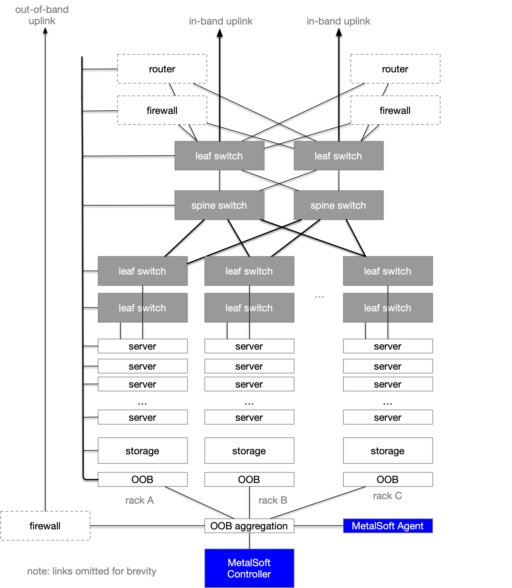
During server registration the system will detect the server-to-switch topology and so there is no need to follow a specific pattern although it is of course recommended to be consistent with cabling for identical servers.
In this diagram we also reference firewalls part of leaf switches that act as “border devices”. We also feature some routers which are sometimes attached to the same border leaf switches that will help route in-band traffic out of the MetalSoft managed infrastructure.
The following is a more complete cabling diagram with the storage network also presented as a separate fabric:

There are several variations possible to this setup:
The data leaf and storage fabrics can be collapsed into a single spine-leaf fabric if maximum storage performance is not a strict requirement and there are enough ports available on the data leafs.
A data leaf pair can also act as border devices if enough ports are available.
The border devices can be absent altogether if the external connections feature is not required.
Production rack cabling guide - No storage
The following shows a setup without storage. Note that if a separate LAN network is required, an additional pair of links are needed to connect each server to the data leafs. These are shown here as dotted lines.

Production rack cabling guide - data & storage fabrics on the same physical leaf switches
The following shows a connection setup for the collapsed version where the same data leaf pairs also host the storage fabric. Note that if a separate LAN network is required, an additional pair of links are needed to connect each server to the data leafs (not shown in the diagram).

Note that the storage appliance is connected using 4 links, two per “head node”, also called “storage controllers”. Some storage arrays feature more links per controller. In that case, connect half of the ports of each “storage controller” to one data/storage leaf switch 1 and the other half to the other data/storage leaf switch 2.
Remember to configure the switch-port->to storage-port connection setup in the MetalSoft application to reflect the chosen configuration as the setup is not auto-detected.
For iSCSI block storage appliances such as Dell PowerMax MetalSoft will automatically create virtual interfaces in which to terminate each storage layer 2 network and will attach them in a round-robin fashion to physical storage appliance uplinks in order to avoid concentrating all traffic on a single SAN uplink. Remember to configure the port-to-virtual-port mappings in the appliance configuration tab.
Production rack cabling guide - separate data & storage fabrics
The following diagram shows the cabling strategy of a production rack that has separate data & storage fabrics.

Note that the storage array is connected using 4 links, two per “head node”, also called “storage controllers”. Some storage arrays feature more links per controller. In that case, connect half of the ports of each “storage controller” to one storage leaf switch and the other half to the other storage leaf switch.
Remember to configure the switch-port->to storage-port connection setup in the MetalSoft application to reflect the chosen configuration as the setup is not auto-detected.
For iSCSI block storage appliances such as Dell PowerMax MetalSoft will automatically create virtual interfaces in which to terminate each storage layer 2 network and will attach them in a round-robin fashion to physical storage appliance uplinks in order to avoid concentrating all traffic on a single SAN uplink. Remember to configure the port-to-virtual-port mappings in the appliance configuration tab.
Control plane (Management network) architecture
Each site or pod is managed via a dedicated MetalSoft Site Controller. When powered on, Site Controllers will connect to the configured Global Controller.

There are different ways in which the MetalSoft Site Controller can be deployed:
On bare metal
As a VM with layer 2 connectivity to the management network
As a VM with a firewall providing security and DHCP relay services
Under normal operation the Site Controller only requires access to the Out of band (management) networks. No in-band access is required.
The only exceptions to the above are when the Site Controller is used for older systems that only support PXE in which case the network setup is different or MetalSoft apps are used in conjunction with deploying the Operating System.
Bare metal Site Controller cabling
The following shows the Site Controller’s cabling if the Site Controller runs directly on a bare metal server. All ports of the OOB switch should be in the same layer 2 broadcast domain (VLAN).

Virtual Site Controller, layer 2 connectivity

The Site Controller can also be hosted as a virtual machine if the layer 2 connectivity can be extended (same VLAN).
Virtual Site Controller, layer 3 connectivity
The following shows the Site Controller’s connectivity if it runs as a VM in some remote virtualization cluster and there is no direct layer 2 connectivity. In this case, the Site Controller is connected via a firewall or router or some other form.
This setup is often used to enforce firewall rules on the Site Controller in order for example to separate the switch management network from the server management network.
To enable ZTP a DHCP relay configuration is required on the firewall or router appliance that will take the DHCP traffic from the server or switch management interfaces to the Site Controller’s embedded DHCP server.

Site Controller cabling - PXE (legacy, deprecated)
Some older equipment does not support virtual media-only setups. MetalSoft can utilize PXE in order to deploy the operating system and coordinate the SAN booting. In order for that to happen an extra link is required between the Site Controller server and the data & storage fabrics.
This can be made with the spine layer or with a leaf switch, in which case the location of the Site Controller server should be inside one of the compute racks.
To improve the security and create a separation between the control plane and the data-plane a router VM which also acts as a firewall is introduced. To save resources the router and the Site Controller are now virtualized and deployed onto the same physical server.
