Provisioning an infrastructure
In the previous steps we have created the logical networks and endpoints on MetalSoft but so far there have been no actual configurations on the switches. Let’s do that now:
1. Create an Infrastructure
Section titled “1. Create an Infrastructure”Let’s go ahead and create an infrastructure for a tenant.
- Go to upper right corner of the admin and click on the circle with the User’s initials. Select Infrastructure Designer (or go to the “burger” menu next to the logo on the left). The infrastructure editor should appear. If there is no infrastructure the system will prompt you to create one:
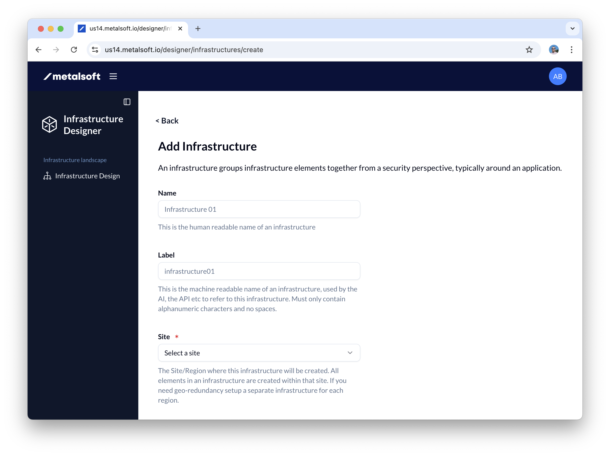
- Name the infrastructure tenant01-infra01
- Select the site in which to create the infrastructure
2. Add endpoints to the infrastructure
Section titled “2. Add endpoints to the infrastructure”- Click Add element
- Select Endpoint
- Input the name of the endpoint added: Server01, label server01
- Select the server from the dropdown of the endpoint.
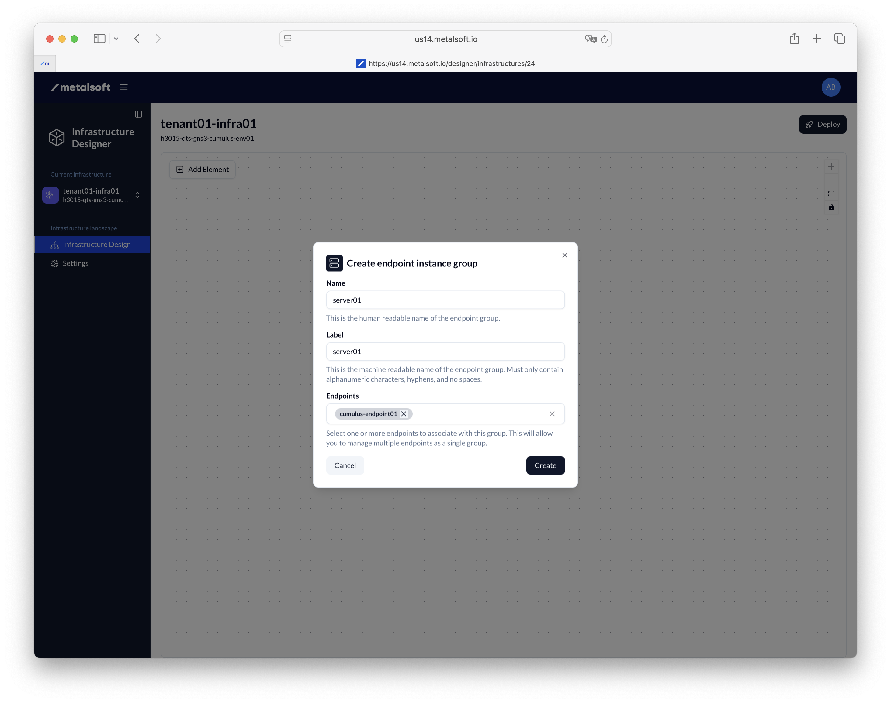
- Repeat the steps above and add the rest of the endpoints
3. Add the pre-created logical network
Section titled “3. Add the pre-created logical network”Add the logical networks to the infrastructure editor.
- Click Add element
- Select pre-created network
- Select the network that you created before
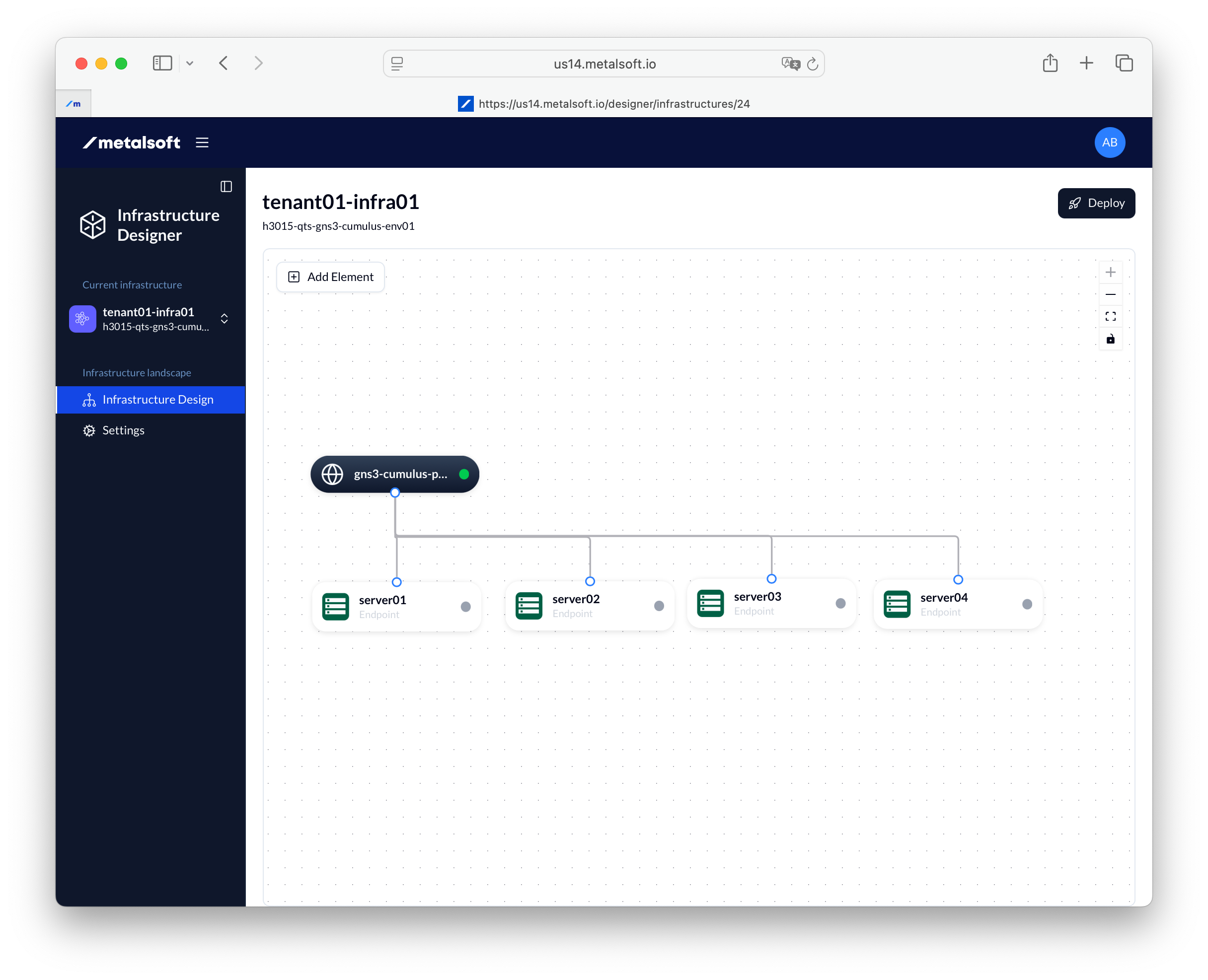
4. Connect the endpoints
Section titled “4. Connect the endpoints”- Select Tagged
- Select Access mode Layer 2
- Select Redundancy: Active-Active
- Select Implementation: Distributed Link Aggregation
5. Deploy the infrastructure
Section titled “5. Deploy the infrastructure”- Click Deploy
- Leave all options as they are
- Click Deploy
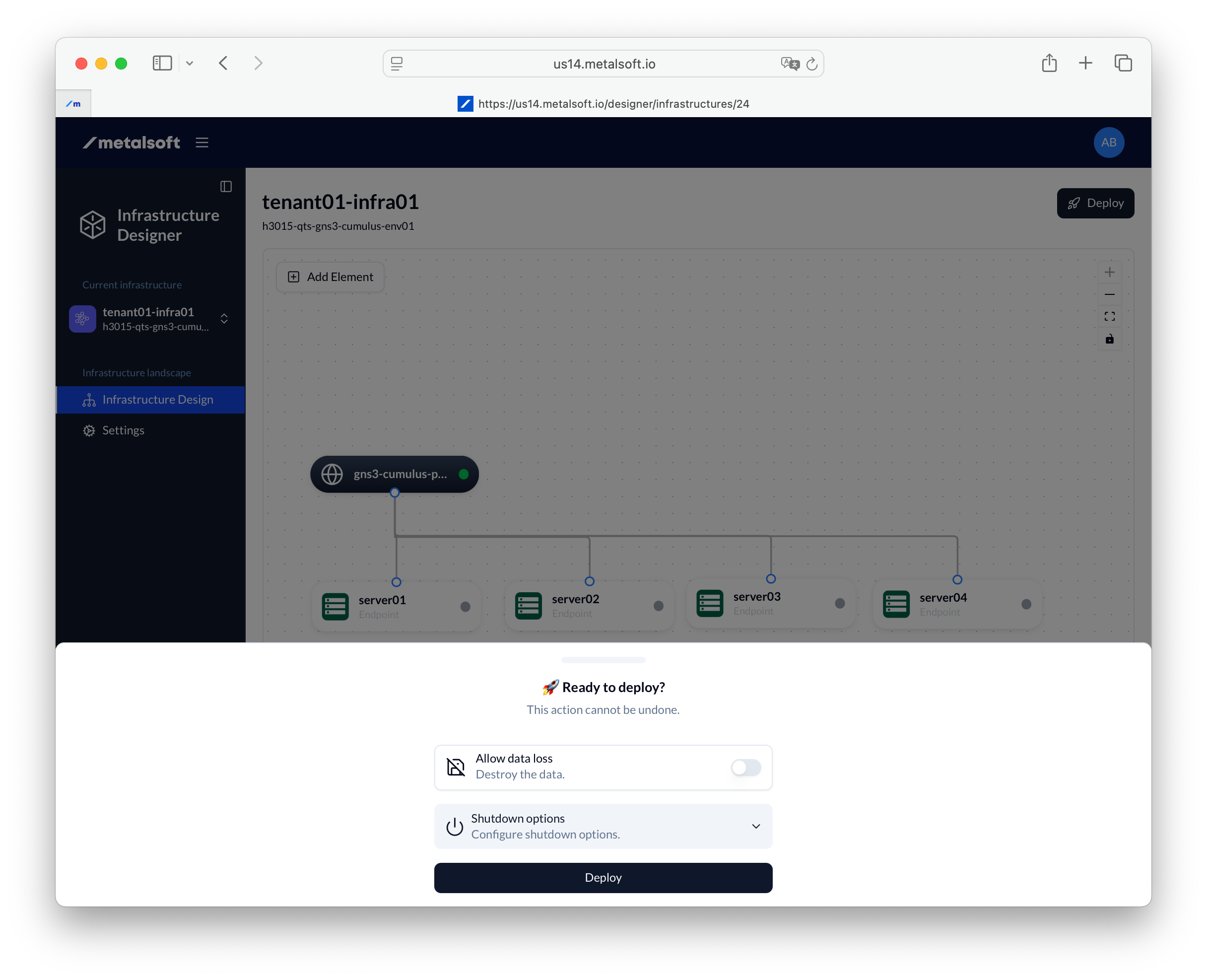
You should now wait for the infrastructure to be deployed. At the end of the deploy all of the switches will have been updated with the configuration required to connect the endpoints to the logical network.
Connection Options
Section titled “Connection Options”The following are the options possible for
- Tagged — If Enabled, the traffic will be sent to (and expected from) the server tagged with the VLAN that was allocated for the respective logical network. If unchecked the traffic will be sent untagged.
- Access mode — Only Layer 2 is currently supported
- Redundancy mode:
- active-backup — One link is active, the other is standby. Traffic fails over if the active link goes down.
- active-active — All links are active simultaneously, providing increased bandwidth and redundancy.
- Implementation type (when redundancy is enabled):
- link-aggregation — Bundles multiple links on the same switch using LACP.
- distributed-link-aggregation — Bundles links across a switch pair (MLAG/VLT/VPC). Requires a switch pair.
- ecmp — Uses Equal-Cost Multi-Path routing across multiple links.
- MTU — Maximum Transmission Unit. Set to override the default configured on the Network Profile or logical network. The largest value will be used.
- Disable auto IP allocation — By default, each endpoint connection to a logical network will receive an IP from each of the subnets listed in the IP allocation strategy.
The following options are available only for servers:
- Provides the default route - If the server is connected to more than two logical networks, and the logical network has a subnet configured in the IP allocation strategy that has a Gatway set, that IP will be set as the default gateway in the operating system.
- Provision Instance DNS records - If the system has a DNS extension registered, it will be invoked to configure the DNS records for the instances of this instance array for all associated IPs created from the subnets configured on the logical network.
- Provision Load Balancing DNS records - If the system has a DNS extension registered, it will be invoked to configure a load-balancing DNS record for ALL the associated IPs created from the subnets configured on the logical network. This can be used to provide DNS-based load-balancing.
Managing infrastructures via the API
Section titled “Managing infrastructures via the API”Creating an infrastructure
Section titled “Creating an infrastructure”curl -X POST "https://<your-server>/api/v2/infrastructures" \ -H "Content-Type: application/json" \ -H "Authorization: Bearer <API_KEY>" \ -d '{ "siteId": 1, "label": "tenant01-infra01" }'Creating an endpoint instance group in an infrastructure
Section titled “Creating an endpoint instance group in an infrastructure”curl -X POST "https://<your-server>/api/v2/infrastructures/{infrastructureId}/endpoint-instance-groups" \ -H "Content-Type: application/json" \ -H "Authorization: Bearer <API_KEY>" \ -d '{ "endpointGroupName": "web-servers" }'Adding an endpoint instance
Section titled “Adding an endpoint instance”curl -X POST "https://<your-server>/api/v2/endpoint-instances" \ -H "Content-Type: application/json" \ -H "Authorization: Bearer <API_KEY>" \ -d '{ "groupId": 1, "endpointId": 10 }'Creating a network connection
Section titled “Creating a network connection”curl -X POST "https://<your-server>/api/v2/endpoint-instance-groups/{endpointInstanceGroupId}/config/networking/connections" \ -H "Content-Type: application/json" \ -H "Authorization: Bearer <API_KEY>" \ -d '{ "logicalNetworkId": 5, "tagged": true, "redundancy": { "mode": "active-active", "implementationType": "distributed-link-aggregation" } }'Deploying an infrastructure
Section titled “Deploying an infrastructure”curl -X POST "https://<your-server>/api/v2/infrastructures/{infrastructureId}/actions/deploy" \ -H "Content-Type: application/json" \ -H "Authorization: Bearer <API_KEY>" \ -d '{ "allowDataLoss": false, "shutdownOptions": { "attemptSoftShutdown": true, "softShutdownTimeoutSeconds": 180 } }'Listing infrastructures
Section titled “Listing infrastructures”curl "https://<your-server>/api/v2/infrastructures" \ -H "Authorization: Bearer <API_KEY>"